
How one can wire pcb mono enter jack? Stage up your audio recreation with this super-detailed information! From fundamental setups to pro-level configurations, we’ll stroll you thru all the pieces it is advisable learn about connecting mono enter jacks to your PCBs. Prepare to beat the world of soldering and sound!
This information dives deep into the world of mono enter jacks, explaining their operate on PCBs, widespread varieties, and the significance of correct wiring for optimum audio efficiency. We’ll cowl all the pieces from the important parts and instruments to detailed wiring procedures and essential PCB structure issues. Plus, we’ll equip you with the troubleshooting expertise to sort out any audio hiccups alongside the best way.
So seize your soldering iron and let’s get wired!
Introduction to Mono Enter Jacks on PCBs
Mono enter jacks are important parts in digital tasks, offering an important interface for connecting audio sources to your circuit. They permit the transmission of audio indicators from gadgets like microphones, devices, or different audio sources to your circuit’s enter stage. Correct understanding and proper wiring of those jacks are paramount for attaining optimum audio high quality and stopping sign degradation.These jacks, usually discovered on numerous PCBs, function the connection level for analog audio indicators.
They translate the mechanical motion or electrical indicators from an exterior machine into {an electrical} sign that may be processed by your circuit. Cautious consideration to wiring particulars and the precise jack sort is significant to make sure the audio sign is transmitted faithfully.
Frequent Sorts of Mono Enter Jacks
Completely different mono enter jacks are designed for numerous functions and supply various ranges of performance. Understanding these variations helps in deciding on the suitable jack in your mission. The commonest varieties embody the 1/4″ TS jack, which is prevalent in musical instrument functions and audio gear. Different varieties could embody specialised connectors for particular duties.
Mono Enter Jack Pinouts and Functions
| Jack Sort | Pinouts | Typical Functions | Picture Description |
|---|---|---|---|
| 1/4″ TS (Tip-Sleeve) | Tip (sign), Sleeve (floor) | Musical devices, microphones, and common audio enter functions. A standard alternative for guitar pickups and microphone inputs as a consequence of its robustness and widespread use. | A 1/4-inch TS jack is soldered to a PCB. The tip of the jack is related to the circuit’s enter sign line, whereas the sleeve is related to the bottom. The connection factors are clearly seen on the PCB, showcasing the easy nature of the wiring. |
| 1/8″ TS (Stereo Mini Jack – Mono Mode) | Tip (sign), Sleeve (floor) | Transportable audio gadgets, pc audio interfaces, and functions the place a smaller jack measurement is fascinating. | A 1/8-inch TS jack is soldered to a PCB, with the tip related to the circuit’s enter sign and the sleeve to the bottom. The compact design of the jack is highlighted within the picture. |
| RCA Jack | Middle (sign), Outer (floor) | Client audio gear, residence theater programs, and video indicators (though primarily used for video, the audio part is suitable with mono indicators). | An RCA jack is soldered to a PCB. The middle pin is the sign, and the outer ring is the bottom connection. The picture shows the bodily configuration of the jack and its connection to the PCB tracks. |
Significance of Appropriate Wiring
Appropriate wiring for mono enter jacks is vital for making certain a transparent and undistorted audio sign. Improper connections can result in noise, sign loss, and even harm to your circuit. A well-wired connection offers the optimum path for the audio sign to circulate, making certain high-quality sound. Fastidiously adhering to the pinout diagrams is important for profitable wiring.
Parts and Instruments Wanted
Crafting a strong and dependable mono enter jack connection on a PCB necessitates cautious number of parts and applicable instruments. This meticulous course of ensures a seamless audio sign path, vital for any digital mission involving sound enter. Correctly chosen parts and elegantly executed wiring contribute to a professional-grade audio expertise.
Important Parts
Selecting the best parts is prime to attaining a steady and high-quality audio enter. A well-selected mono enter jack, together with matching wires and solder, are essential for profitable wiring. These parts, when mixed appropriately, set up a strong connection for sign transmission.
- Mono Enter Jack: A vital part, the mono enter jack offers the bodily connection level for audio indicators. Deciding on the suitable jack sort (e.g., 1/4 inch, 1/8 inch) is important, matching it to the supposed utility and the precise audio supply. Think about elements just like the anticipated impedance of the audio sign supply when selecting the enter jack.
- Solder: Excessive-quality solder ensures a robust and dependable connection between the jack’s pins and the PCB traces. Use rosin-core solder for its flux properties, which aids within the soldering course of. Make sure the solder is suitable for the precise gauge of wire getting used to stop points through the course of.
- Wires: Correctly chosen wires are important for carrying the audio sign between the enter jack and the PCB. Utilizing stranded wire is advisable for flexibility and minimizing sign degradation. Think about the gauge of the wire (e.g., 22 AWG, 24 AWG) to make sure it could deal with the sign with out extreme resistance.
- Insulation Tape/Warmth Shrink Tubing: Correct insulation is vital for stopping quick circuits and making certain sign integrity. Insulation tape or warmth shrink tubing are used to cowl uncovered wires, defending them from exterior interference. Select an acceptable insulation materials based mostly on the working atmosphere of the circuit.
Important Instruments
The fitting instruments are instrumental in attaining a exact and professional-quality connection. These instruments guarantee accuracy and effectivity within the wiring course of.
- Soldering Iron: A soldering iron is important for creating dependable solder joints. The wattage of the iron ought to be applicable for the kind of solder getting used. A variable temperature setting is helpful for fine-tuning the soldering course of.
- Soldering Station: A soldering station with a temperature management offers extra exact management over the soldering course of, minimizing potential points like overheating or underheating. A soldering station can enhance the consistency and high quality of the solder joints.
- Wire Strippers/Cutters: Correct wire preparation is essential. Wire strippers/cutters are important for eradicating the insulation from the wires and making certain clear cuts. These instruments contribute to the general high quality and reliability of the connection.
- Multimeter: A multimeter is invaluable for verifying continuity and measuring resistance throughout the connection. This ensures the connection is undamaged and practical. A multimeter permits for correct testing and troubleshooting of the circuit.
Part Choice Pointers
Cautious consideration of utility necessities is vital to deciding on the right parts. The kind of audio supply, the anticipated sign power, and the environmental situations all affect part selections. Matching the enter jack to the audio supply is essential for sign integrity and optimum efficiency.
| Part | Description | Specs | Picture Description |
|---|---|---|---|
| Mono Enter Jack | Audio enter jack | 1/4 inch, solder-compatible, gold-plated contacts | A transparent picture of a 1/4 inch mono enter jack, showcasing the solder factors and the gold-plated contacts. Be aware the pin association and the bodily dimensions of the jack. |
| Solder | Offers the connection between parts | Rosin-core, 60/40 lead-free solder, applicable gauge for the wire used | An in depth-up picture of the solder, highlighting its consistency and the rosin-core. |
| Wire | Connects the enter jack to the circuit | Stranded, 22 AWG, insulated, applicable size | A size of wire, exhibiting its stranded building and insulation. |
| Insulation Tape | Protects uncovered wires | Warmth-resistant, applicable colour for visibility | A roll of insulation tape, highlighting its texture and adhesive properties. |
Wiring Procedures for Completely different Varieties
Embarking on the thrilling journey of connecting a mono enter jack to your PCB is a rewarding expertise. This course of, although seemingly simple, requires precision and understanding. Mastering the right wiring procedures ensures optimum audio efficiency and avoids potential points. This part will information you thru the assorted wiring strategies, highlighting vital issues for various kinds of jacks and PCB layouts.A well-executed wiring process not solely ensures performance but additionally contributes to the general high quality and reliability of your mission.
Consideration to element on this step will stop irritating troubleshooting afterward. Let’s dive into the specifics of wiring procedures, exploring the completely different approaches and addressing potential challenges.
Customary Mono Enter Jack Wiring
Understanding the basic wiring process for the standard mono enter jack is essential for any electronics fanatic. This entails connecting the tip, sleeve, and ring to the suitable sign strains in your PCB. A meticulous strategy is vital to success.
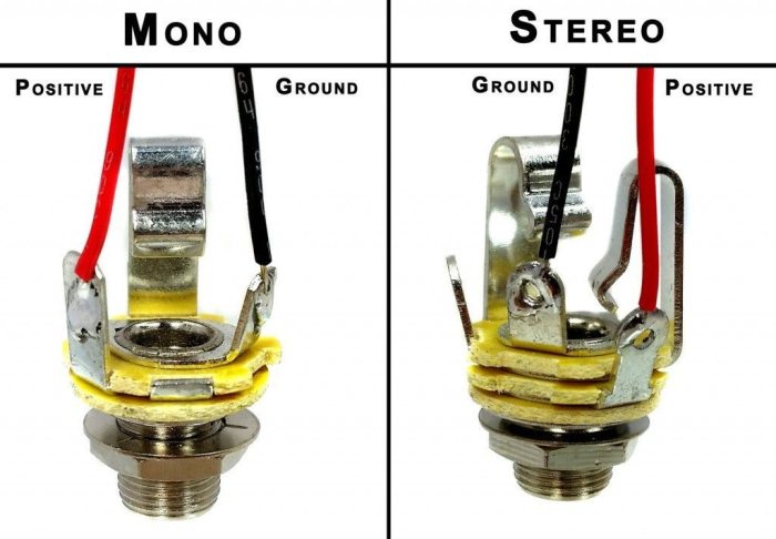
- Determine the tip, sleeve, and ring terminals on the mono enter jack. The tip sometimes carries the audio sign, the sleeve is the bottom connection, and the ring is commonly unused.
- Find the corresponding sign and floor strains in your PCB. Confer with your circuit diagram for correct pinouts.
- Use applicable solder to attach the tip of the jack to the audio sign line on the PCB. Guarantee a robust, dependable solder joint.
- Join the sleeve of the jack to the bottom line on the PCB, making a steady floor connection. A strong solder connection is vital for stopping sign interference.
- If the ring terminal is current, guarantee it’s both soldered to the PCB’s floor or left unconnected. This will depend on the precise circuit design. Comply with your circuit diagram.
- Check the connection by making use of a sign supply to the enter jack. Observe the output for a transparent and constant sign. Pay shut consideration to any distortion or undesirable noises.
Wiring Procedures for Completely different Sorts of Mono Enter Jacks
Completely different mono enter jacks may need barely diverse pinouts. Understanding these variations is essential for profitable wiring. This part particulars learn how to deal with various kinds of jacks.
- Some mono enter jacks could have a separate floor connection. In these circumstances, be certain that the corresponding floor line on the PCB is related to the jack’s floor terminal. The right identification and connection of the bottom terminal are important for avoiding quick circuits.
- Different varieties may need a further ring terminal. This extra terminal could also be used for particular features, equivalent to switching or extra sign conditioning. At all times confer with the precise jack’s datasheet or circuit diagram.
- At all times be certain that the jack is appropriately oriented on the PCB. The orientation of the jack will have an effect on the right wiring connections. It is a essential step in stopping errors.
Comparability of Wiring Strategies for Completely different PCB Layouts
Completely different PCB layouts can affect the optimum wiring strategies. This part highlights how completely different approaches cater to completely different PCB constructions.
- A through-hole PCB structure could necessitate longer solder connections. Cautious consideration to solder joints and avoiding extra solder is important to keep up circuit integrity.
- Floor-mount PCBs usually require smaller solder joints. Use the suitable soldering instruments and methods to create dependable connections with minimal extra solder.
- Think about the proximity of parts. Strategic placement of parts and enter jacks minimizes the danger of quick circuits and improves sign integrity.
Soldering Strategies for PCB Wiring
Numerous soldering methods exist, every with its personal benefits and issues. Selecting the best technique is essential for profitable wiring.
- Utilizing a soldering iron with applicable temperature settings is important. Extreme warmth can harm parts, whereas inadequate warmth ends in weak solder joints.
- Guarantee correct solder utility. An excessive amount of solder can create bridges and quick circuits, whereas inadequate solder ends in weak joints.
- Apply applicable soldering methods. Apply on scrap PCBs or parts earlier than working in your primary mission to make sure proficiency.
Potential Points and Troubleshooting Steps
Troubleshooting wiring points is an important ability for any electronics fanatic. This part particulars widespread issues and options.
- Frequent issues embody solder bridges, weak solder joints, and incorrect wiring. Study all connections for these points.
- To deal with solder bridges, rigorously take away the surplus solder utilizing a solder sucker. Be cautious to keep away from damaging the PCB or parts.
- If the connection is weak, reheat the joint with a soldering iron and reapply solder. Make sure the joint is correctly fashioned.
- Double-check the wiring diagram and be certain that all connections are appropriate. A cautious evaluation is commonly step one in figuring out the basis trigger.
Circuit Diagrams and Schematics: How To Wire Pcb Mono Enter Jack
Unlocking the potential of your mono enter jack requires a deep understanding of its circuit diagrams and schematics. These visible representations act as blueprints, guiding you thru the intricate pathways of audio indicators as they journey from the jack to your audio processing parts. By understanding these diagrams, you acquire the power to customise and optimize your audio circuits for particular wants and functions.An intensive examination of circuit diagrams and schematics lets you analyze the circulate of audio indicators, establish potential sign degradation factors, and implement essential protecting measures.
This data empowers you to create strong and dependable audio programs that ship high-quality sound.
Instance Mono Enter Circuits
Numerous circuit configurations will be employed for connecting a mono enter jack to an amplifier. Every configuration presents a novel set of benefits and downsides, making it important to decide on the suitable circuit based mostly in your particular utility necessities.
- Easy Enter Circuit: This circuit offers a direct connection between the enter jack and the amplifier’s enter. It is the best and most cost-effective possibility, nevertheless it lacks inherent safety in opposition to overloads and different potential points. This simple strategy is commonly ample for low-level audio functions, however strong safety measures are essential for functions with the next potential for sign surges.
- Buffered Enter Circuit: This circuit makes use of a buffer amplifier to isolate the enter jack from the amplifier’s enter. This isolation enhances sign high quality and prevents the amplifier’s enter traits from affecting the enter jack. This buffering characteristic enhances the steadiness and resilience of the circuit by mitigating the consequences of variations within the amplifier’s enter impedance.
- Enter Circuit with Safety: This circuit contains diodes or different parts to guard the amplifier from overvoltages or quick circuits. This further layer of safety safeguards the fragile parts of the amplifier and ensures the longevity of the audio system. These protecting measures are paramount in high-power audio functions, the place there’s a larger danger of injury from sudden surges in sign power.
Comparability of Completely different Circuit Diagrams
The next desk summarizes the important thing traits of various mono enter jack circuit diagrams.
| Circuit Diagram | Description | Benefits | Disadvantages |
|---|---|---|---|
| Easy Enter Circuit | Direct connection from the enter jack to the amplifier’s enter. | Simple to implement, low price. | Restricted safety in opposition to overloads and quick circuits. |
| Buffered Enter Circuit | Makes use of a buffer amplifier to isolate the enter jack from the amplifier’s enter. | Improved sign high quality, enhanced stability, and lowered susceptibility to variations within the amplifier’s enter impedance. | Elevated complexity and value in comparison with the straightforward enter circuit. |
| Enter Circuit with Safety | Contains diodes or different parts to guard the amplifier from overvoltages and quick circuits. | Enhanced safety for the amplifier, making certain system longevity. | Elevated complexity and potential for slight sign attenuation. |
Schematics for Completely different Audio Functions
The particular schematic in your audio utility will rely on elements just like the required sign ranges, the kind of amplifier, and any obligatory safety measures.
Illustrative examples of schematics for various audio functions are offered beneath:
- Mic Preamplifier Circuit: This schematic incorporates a microphone preamplifier to spice up the low-level sign from a microphone. The preamplifier offers an acceptable sign degree for the enter stage of an amplifier or recording machine. This enables the recording machine to seize the delicate nuances of the microphone sign, leading to a high-fidelity recording.
- Line-Stage Enter Circuit: This schematic handles line-level indicators from an audio supply. The circuit offers a direct connection to the amplifier enter, appropriate for audio indicators from gadgets equivalent to CD gamers, cassette gamers, or different audio playback gadgets. This direct strategy is essential for sustaining the integrity of the audio sign and avoiding sign loss.
Part Roles within the Circuit
The roles of various parts in these circuits are vital to understanding their performance. Resistors, capacitors, and diodes every contribute particular duties, like impedance matching, filtering undesirable indicators, and defending the circuit from harm. A deep understanding of those parts permits for knowledgeable modifications to the circuit, permitting for optimization for explicit functions.
PCB Format Concerns

Crafting a high-quality audio circuit necessitates meticulous consideration to element, significantly within the PCB structure for the mono enter jack. Correct placement and routing of traces instantly affect sign integrity, influencing the general efficiency and reliability of the audio system. Cautious consideration of those elements ensures a strong and clear audio path.The structure of the enter jack on the PCB ought to be designed with the aim of minimizing sign degradation, noise pickup, and impedance mismatches.
The bodily association of parts and traces considerably impacts the circuit’s capacity to faithfully transmit audio indicators. This part delves into essential features of PCB structure for mono enter jacks, emphasizing methods for attaining optimum sign integrity.
Hint Width and Size
Hint width and size are vital parameters affecting sign integrity. Wider traces present decrease resistance and capacitance, facilitating sooner sign propagation and decreasing sign loss. Conversely, excessively broad traces can result in elevated parasitic capacitance and inductance, hindering sign high quality. Likewise, longer traces can introduce important sign delay and attenuation. Sustaining an applicable stability between hint width and size is significant for optimum sign transmission.
Floor Airplane Concerns
Implementing a strong floor airplane is important for minimizing noise. A well-defined floor airplane offers a low-impedance path for present, successfully suppressing noise and crosstalk. A steady floor airplane beneath the vital traces and parts is essential. This airplane ought to be related to the bottom pins of the enter jack and the circuit’s floor level.
Part Placement
Strategic part placement is equally vital. Parts ought to be positioned to attenuate undesirable coupling and electromagnetic interference. Parts producing excessive frequencies or excessive currents ought to be positioned away from delicate circuits or parts. Conserving high-frequency parts, equivalent to capacitors, away from the enter jack and audio sign paths, minimizes the prospect of sign degradation and noise.
Routing Concerns
Cautious routing of traces is essential to keep away from sign reflections and noise. Traces ought to be routed in a way that minimizes sharp bends and discontinuities. Sharp bends can introduce important reflections, distorting the audio sign. Straight, easy routing paths decrease these results. Routing traces removed from high-frequency parts additional minimizes interference.
Greatest Practices for PCB Format, How one can wire pcb mono enter jack
| Format Consideration | Clarification | Impression on Sign Integrity | Instance Picture |
|---|---|---|---|
| Hint Width | The width of the traces connecting the jack to the circuit. Wider traces supply decrease resistance and capacitance. | Impacts sign pace and noise. Wider traces scale back sign loss and enhance pace. | A picture depicting a magnified view of a hint with an applicable width, exhibiting a easy, uniform cross-section. |
| Hint Size | The size of the traces connecting the jack to the circuit. | Impacts sign delay and attenuation. Shorter traces decrease sign degradation. | A schematic exhibiting completely different hint lengths and their affect on sign timing. |
| Floor Airplane | A steady floor airplane beneath the vital traces and parts. | Minimizes noise and crosstalk by offering a low-impedance path for present. | A schematic diagram illustrating a well-defined floor airplane connecting to the enter jack’s floor pin and the circuit’s floor level. |
| Part Placement | Strategic positioning of parts to attenuate undesirable coupling and electromagnetic interference. | Reduces noise and sign distortion by separating high-frequency and high-current parts from delicate circuits. | A structure diagram highlighting the positioning of parts, with high-frequency parts evaded the enter jack and audio sign paths. |
| Hint Routing | Cautious routing of traces to keep away from sign reflections and noise. | Minimizes sign distortion by avoiding sharp bends and discontinuities. | A schematic diagram illustrating correct hint routing with easy, straight paths and minimal bends. |
Testing and Troubleshooting
Efficiently wiring your mono enter jack is a major step in making a practical audio circuit. Now, let’s unlock the secrets and techniques to assured troubleshooting, making certain your mission performs flawlessly. A well-tested circuit is a dependable circuit, and understanding the testing course of is vital to a rewarding expertise.Thorough testing and troubleshooting are essential for making certain the performance and reliability of your wired mono enter jack.
Figuring out and resolving points early saves time and frustration, finally resulting in a extra satisfying mission final result. The method of diagnosing and fixing issues is a helpful ability, relevant to many features of electronics and problem-solving on the whole.
Testing the Wired Mono Enter Jack
To make sure correct performance, the wired mono enter jack have to be rigorously examined. This entails verifying the sign path, confirming correct impedance matching, and detecting any potential noise or interference. Cautious consideration to element throughout this stage will decrease points and assure a easy audio sign.
- Visible Inspection: Fastidiously study the wiring connections for any free or broken parts. Guarantee all solder joints are safe and the wires are correctly terminated. A well-maintained circuit is a robust and dependable circuit.
- Continuity Testing: Use a multimeter to test the continuity of the wiring. This ensures there aren’t any breaks or shorts within the sign path. Confirm the connection between the enter jack’s pins and the circuit’s parts.
- Sign Verification: Apply a recognized audio sign to the enter jack and monitor the output. This helps decide if the sign is being transmitted appropriately. An audio generator is important right here for exact sign testing.
Figuring out and Resolving Frequent Wiring Points
Frequent wiring points can considerably affect the efficiency of the mono enter jack. Figuring out and resolving these points promptly is essential.
- Free Connections: A free connection can result in intermittent sign issues or an entire lack of sign. Tightening the connections is a standard resolution to this subject. Common upkeep and inspection can stop this downside from recurring.
- Incorrect Polarity: In some circumstances, the wiring could have incorrect polarity. Checking and correcting this subject is essential to the correct performance of the circuit. This may occasionally end in an inverted or muted audio sign.
- Floor Loops: Floor loops could cause undesirable noise within the audio sign. Figuring out and resolving floor loops is a vital step in attaining clear audio. Use a floor reference level and preserve correct grounding practices all through the circuit.
Troubleshooting Sign Issues
Sign issues can manifest in numerous methods, from muted audio to distorted indicators.
- Sign Attenuation: Sign attenuation happens when the sign power decreases alongside the transmission path. This may be as a consequence of excessive impedance or extreme wire size. Utilizing high-quality parts and shorter wiring runs are potential options.
- Sign Distortion: Distorted indicators may end up from inadequate sign amplification or part harm. Checking the sign power at numerous factors within the circuit helps establish the issue space. Guarantee ample amplification levels if required.
- Sign Dropouts: Sign dropouts, or intermittent sign loss, can point out an issue with the connection or the parts. Confirm the connections, test for free connections, and guarantee all parts are in correct working order. Pay explicit consideration to the steadiness of solder joints.
Troubleshooting Noise Points
Noise within the audio sign will be disruptive and ugly. Numerous methods will help establish and resolve the problem.
- Exterior Noise Sources: Exterior sources of noise will be mitigated by shielding the circuit or utilizing filtering methods. Utilizing shielded cables and grounding the circuit successfully will scale back noise.
- Floor Noise: Floor noise is a standard supply of interference in audio circuits. Making certain correct grounding practices and utilizing a floor reference level are important steps in mitigating floor noise. Correct grounding will decrease noise and make sure the stability of the circuit.
- Improper Filtering: Inadequate filtering can permit undesirable frequencies to go by, creating noise within the audio sign. Utilizing applicable filtering methods, equivalent to capacitors and inductors, can successfully scale back noise. Cautious number of filter parts is vital for efficient noise discount.
Finish of Dialogue
Wiring a mono enter jack to your PCB simply acquired a complete lot simpler! This complete information lined all the pieces from the basic ideas to superior troubleshooting. You have realized how to decide on the suitable parts, carry out the wiring procedures, design the PCB structure, and check your work. Now you are able to rock your audio tasks with confidence! Keep in mind, follow makes excellent, so get soldering and unleash the sonic potential of your creations!
FAQ Abstract
What sort of instruments do I want for this mission?
You may want a soldering iron, solder, wire strippers, a multimeter, and tweezers. Security glasses are additionally a should!
What are some widespread errors when wiring mono enter jacks?
Incorrect solder joints, incorrect pin connections, and poor PCB structure are widespread pitfalls. Cautious consideration to element is vital to keep away from these errors!
How do I troubleshoot if my audio is not working?
Begin by checking the connections, then confirm the parts’ correct performance utilizing a multimeter. If the sign is weak, test the hint width and routing in your PCB. In case you’re nonetheless caught, seek the advice of on-line boards or communities!
What are the various kinds of mono enter jacks?
Frequent varieties embody 1/4″ TS jacks, usually used for devices and microphones. Understanding the pinouts (Tip, Ring, Sleeve) is essential for correct wiring.
